Automatic electromagnetic dry powder iron separator
● Purpose
Used to remove magnetic impurities from dry powder materials, primarily including: new energy battery materials (NMC materials, NMC precursors, lithium iron phosphate, lithium iron phosphate, lithium carbonate, lithium hydroxide, anode graphite, silicon-carbon anode, sodium-ion battery materials, etc.), food products, quartz materials, and more.

● Working principle
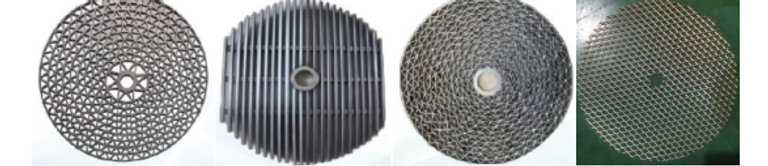
When the electromagnetic coil is energized, it forms a magnetic circuit with the carbon steel casing. The magnetic conductive medium in the hollow cavity concentrates the magnetic field, creating a high-intensity and high-gradient separation.
As the material passes through the magnetic concentration medium, non-magnetic material falls from the outlet while magnetic substances are adsorbed onto the medium. The bottom of the material channel is equipped with a three-way diverting valve, which automatically separates magnetic impurities from the material via a flipping plate controlled by a PLC. Vibration devices installed at both ends of the discharge tube use high-frequency amplitude to enhance material throughput. Transformer oil circulates for cooling, ensuring the coil remains in a safe state. The system employs an HMI (Human-Machine Interface) for operation and PLC-based fully automatic control, enabling automatic iron removal, automatic slag discharge, automatic alarm functions, and unmanned automatic operation with status monitoring.
● Process flow


● Improvements and innovations
Since the production of the first unit, as we have gained deeper understanding of customer applications, we have made many improvements to the equipment to better meet customer needs.
1. The first unit;
2. Changed the inclination angle of the diverter valve for smoother material discharge;
3. Reduced the size of the magnetic material outlet, making the overall structure lighter;
4. Optimized pipeline routing, resolving oil leakage and sealing issues while improving aesthetics;
5. Upgraded the vibration damping device, addressing initial fracturing problems;
6. Used special material tubing for electromagnetic coil connections, greatly enhancing coil safety; gradually increased output voltage.
7. In constant current design, based on the formula I = U/R, when coil resistance increases, the output voltage is gradually raised to maintain a constant current. With P = U*I, if the current remains unchanged and voltage increases, the power change is minimal, meaning the magnetic field strength also changes very little.
To date, the equipment has won customer trust and praise for its stable operational performance and extremely low failure rate.
● Main parameters